MIL-DTL-9320E
permitted. The design shall be completely composed of solid-state circuitry and shall not contain
moving parts.
3.3.1 Adjustment. The warning signal shall be permanently adjusted at the time of
manufacture and shall not require further adjustments.
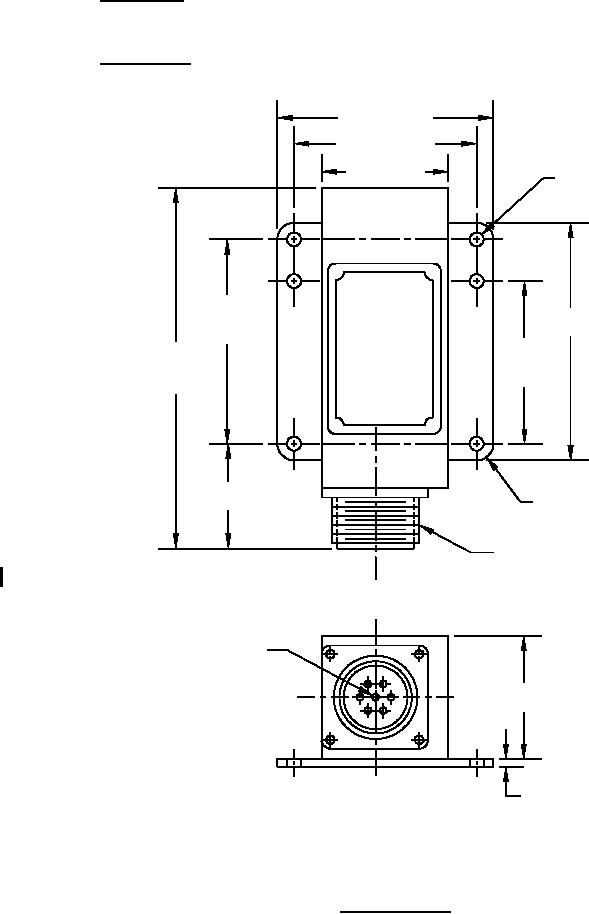
3.3.2 Connections. Connections to the warning signal shall be made as shown on figure 1.
2.50 MAX.
2.125 ±.010
(MAX
Ø 0.173 +0.005
1.50 REF.)
-0.001
2.500
3.00 MAX.
±0.010
1.921
5.00
±0.010
(MAX. REF.)
1.00 MAX.
0.19R (TYP)
CONNECTOR
TO MATE WITH
SAE AS31061-165-15
FLASHING LIGHT
OUTPUT SHALL BE
CONNECTED TO PIN G
1.50 MAX.
OF CONNECTOR
0.094 MAX.
Dimensions in inches.
Decimals 0.XX ±0.03.
FIGURE 1. Warning signal.
4
For Parts Inquires submit RFQ to Parts Hangar, Inc.
© Copyright 2015 Integrated Publishing, Inc.
A Service Disabled Veteran Owned Small Business